add16 diagram
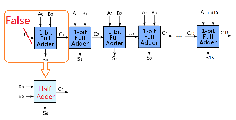
Paste the URL to your image file or drag it from your desktop onto the dialog. Marks 0 Full Adder 25 marks 0.

Nt2fjpkozzwnsm
6 pts Draw the block diagram that describes the following Verilog code.

. DSP_add16 short restrict x short restrict y short restrict r int nx. Design Draw circuit diagrams for each of the following gates. Module add16 input150 a input150 b input cin.
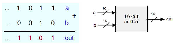
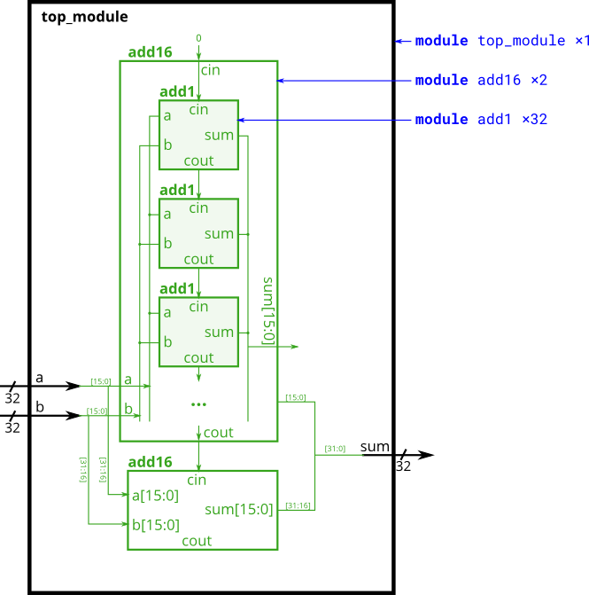
A 16 b 16 Outputs. 0 Half Adder 25. You are given a module add16 that performs a 16-bit addition.
16-bit Adder chip is used to add two 16-bit numbers. Out a b. Select Arrange Insert Image.
Module Add16A B S. DSP_add16_cnc is the natural C equivalent of the. You need to expand your add16 module to support carry in and out.
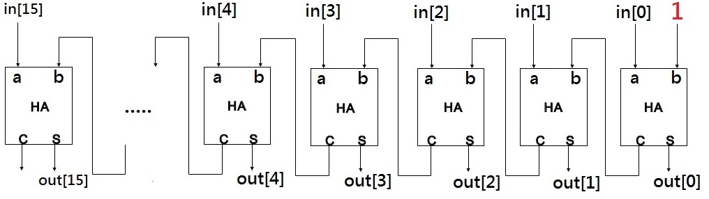
Here we have used two half-adder diagrams to make the full adder diagram. The adder and subtractor have to be merged - Global College Assignment Help - Online Writers 2021 - South Africa Assignments -. Your 32-bit adder does not.
Step 1 of the process MOV AR7 Move the low-byte into the accumulator ADD AR5 Add the second low-byte to the accumulator MOV R3A Move the answer to the low-byte of the. While this diagram is not a 16-bit binary incrementer the implementation is similar to this. Connect the add16 modules together as shown in the diagram below.
The function in the above abstraction can. The provided module add16 has the following declaration. In Solution Explorer right-click the project node and then choose Add New Item.
You can draw for paper then give me screen short. Add a blank class diagram to. Build a miniALU using custom component of nandgame.
Alternatively click the icon in the toolbar then select Image. One add16 module computes the lower 16 bits of the addition result while the second add16 module computes the upper 16 bits of the result. One add16 module computes the lower 16 bits of the addition.
Collaboration diagram for DSP_add16. This commit does not belong to any branch on this repository and may belong to a. Implementation of 16-bit Incrementer Chip in HDL.
Instantiate two of them to create a 32-bit adder. Add a blank class diagram to a project. You have to show all the inputs outputs intermediate signals and blocks modules.
From there theres another module named Add16 that has its own internal wiring this case using half adders and full adders though in real-world languages its probably a language primitive. Your diagram does not match your code your diagram shows a carry connection but your code does not. Add16 inc16 ALU 03 bit Register RAM8 RAM64 RAM512 RAM4K RAM16K pc 04 summary Powered by GitBook.
The Add New Item dialog opens. Add16 16-bit Adder Chip.

Circuitverse 16 Bit Adder Sub
Circuitverse Projprincipal

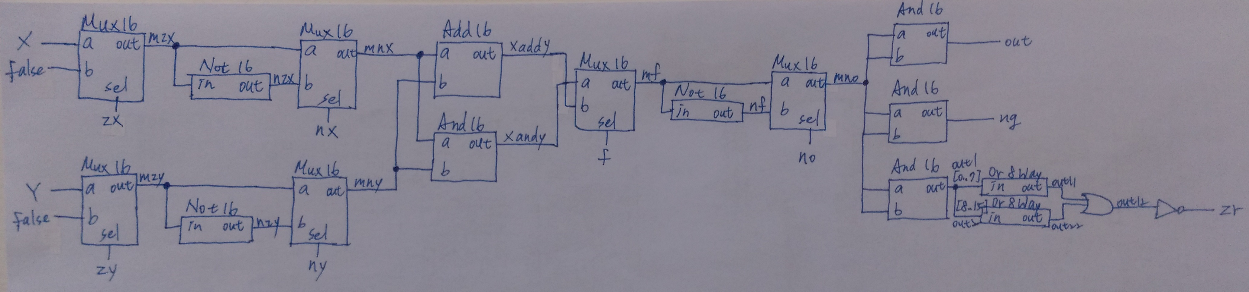
Alu In Detail Tutorials

Fused Information Of Deeplabv3 And Transfer Learning Model For Semantic Segmentation And Rich Features Selection Using Equilibrium Optimizer Eo For Classification Of Npdr Lesions Sciencedirect
Add16 Nand2tetris Homework
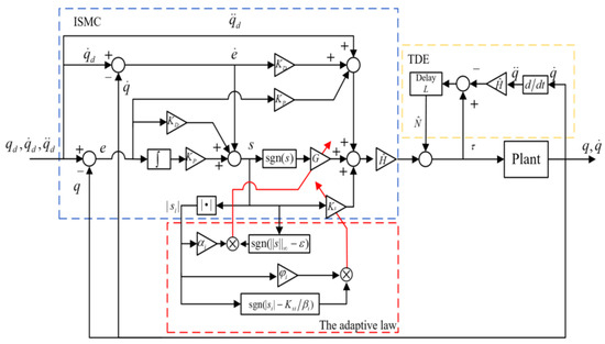
Aerospace Free Full Text Tde Based Adaptive Integral Sliding Mode Control Of Space Manipulator For Space Debris Active Removal Html

Logic Gates Building An Alu

Let S Play Nand Game Part 3 The Alu Youtube

Heating Issue Home Automation Arduino Forum

Nand2tetris With Diagrams Part 5 Binary Arithmetic Half Adder Full Adder Youtube
Inc16 Nand2tetris Homework

Sample Project In Cfc Simatic Simatic Modbus Tcp Communication Using Cp 343 1 And Id 103447617 Industry Support Siemens
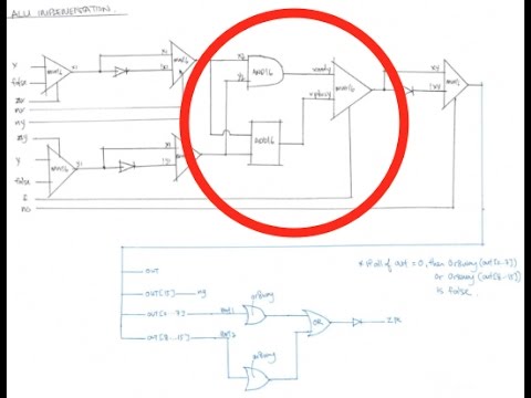
Nand2tetris With Diagrams Part 7 Alu Implementation Youtube
Module Fadd Hdlbits
Project 2 Nand2tetris Homework

Logic Gates Building An Alu
Add16 Nand2tetris Homework